Product Description
Model Number: ISO219-40-150
valve:QF-2C
Material: Steel 37Mn
new seamless steel gas cylinder for N2,O2
Industrial nitrogen Gas
Pressure: High
Place of Origin: China (Mainland)
Brand Name: DSW
Thickness of seamless:5.7mm
weight of seamless: 47to 50kg
working pressure:150bar
test pressure: 250bar
TP:250KG/CM2
PW:150KG/CM2
| 40L and 50L cylinders |
|||||||
| Type | (mm) Outside Diameter |
(L) Water Capacity |
(mm)
Height |
(Kg) Weight(Without valve,cap) |
(Mpa) Working Pressure |
(mm) Design Wall Thickness |
Material Grades |
| ISO232-40-150 | 219 | 40 | 1167 | 43 | 200 | 5.2 | 37Mn |
| ISO232-47-150 | 47 | 1351 | 49 | ||||
| ISO232-50-150 | 50 | 1430 | 51.6 | ||||
| ISO232-40-200 | 232 | 40 | 1156 | 44.9 | 200 | 5.2 | 34CrMo4 |
| ISO232-46.7-200 | 46.7 | 1333 | 51 | ||||
| ISO232-47-200 | 47 | 1341 | 51.3 | ||||
| ISO232-50-200 | 50 | 1420 | 54 | ||||
| EN232-40-210 | 232(TPED) | 40 | 1156 | 44.9 | 230 | 5.8 | 34CrMo4 |
| EN232-46.7-210 | 46.7 | 1333 | 51 | ||||
| EN232-47-210 | 47 | 1341 | 51.3 | ||||
| EN232-50-210 | 50 | 1420 | 54 | ||||
| EN232-40-230 | 40 | 1156 | 44.9 | 230 | 5.8 | 34CrMo4 | |
| EN232-46.7-230 | 46.7 | 1333 | 51 | ||||
| ISO232-47-230 | 47 | 1341 | 51.3 | ||||
| ISO232-50-230 | 50 | 1420 | 54 | ||||
| ISO267-40-150 | 267 | 40 | 922 | 43.3 | 150 | 5.8 | 37Mn |
| ISO267-50-150 | 50 | 1119 | 51.3 | ||||
100% new high quality seamless steel pipe from Bao Shan Iron co.,ltd (Baosteel).
Total 5 working line make 3000pcs per day for oxygen gas cylinder, argon gas cylinder, helium gas cylinder, Nitrogen gas cylinder , Co2 gas cylinder, N2O gas cylinder..etc
China top 1 advanced heat treatment machine. And China top 1 internal polishing machine to make high purity gas cylinder with 99.999% oxygen gas, helium gas, N2O gas and argon gas.
100% Hydrostatic prssure test and leakage test to keep the quality
Advanced automatic spraying working line make the spraying at high top quality , no any bubble , without shrinkage and distoration .
Japan imported shoulder marking machine make it the most qualified ones .
DSW seamless gas cylinder have nice appearance shoulders because we use shape-correction machine treatment make the cylinder shoulder most beautiful shape which other supplier can’t be compared.
Laboratory test standard ISO9809-3 and ISO9809-1, DOT-3AA, EN1964,GB5099 ..etc
Specification
| RECORD OF HYDROSTATIC TESTS ON CYLINDERS TIME ≥ 60S |
||||||||
| S.N | Serial No. | The weight without valve&cap(kg) | Volumetric Capacity(L) | Total expansion(ml) | Permanent expansion(ml) | Percent of Permanent to totalexpanison(%) | Test Pressure 250Bar | Lot and Batch No. |
| 401 | 2070968 057 | 48.6 | 40.0 | 200.3 | 2.6 | 1.3 | 250 | 2070968 |
| 402 | 2070968 058 | 48.3 | 40.0 | 204.2 | 2.3 | 1.1 | 250 | 2070968 |
| 403 | 2070968 059 | 48.2 | 40.1 | 205.1 | 2.6 | 1.3 | 250 | 2070968 |
| 404 | 2070968 060 | 48.5 | 40.1 | 195.2 | 2.6 | 1.3 | 250 | 2070968 |
| 405 | 2070968 061 | 48.2 | 40.1 | 205.1 | 2.7 | 1.3 | 250 | 2070968 |
| 406 | 2070968 062 | 48.6 | 40.0 | 206.2 | 2.2 | 1.1 | 250 | 2070968 |
| 407 | 2070968 063 | 48.3 | 40.3 | 193.9 | 2.2 | 1.1 | 250 | 2070968 |
| 408 | 2070968 064 | 48.0 | 40.1 | 200.1 | 2.9 | 1.4 | 250 | 2070968 |
| 409 | 2070968 065 | 48.4 | 40.0 | 205.2 | 2.9 | 1.4 | 250 | 2070968 |
| 410 | 2070968 066 | 47.9 | 40.1 | 200.1 | 2.6 | 1.3 | 250 | 2070968 |
| 411 | 2070968 067 | 47.9 | 40.2 | 201.0 | 2.2 | 1.1 | 250 | 2070968 |
| 412 | 2070968 068 | 48.7 | 40.0 | 200.3 | 3.0 | 1.5 | 250 | 2070968 |
| 413 | 2070968 069 | 48.3 | 40.2 | 201.0 | 2.8 | 1.4 | 250 | 2070968 |
| 414 | 2070968 070 | 48.2 | 40.1 | 197.2 | 2.5 | 1.3 | 250 | 2070968 |
| 415 | 2070968 071 | 47.9 | 40.0 | 206.2 | 2.6 | 1.3 | 250 | 2070968 |
| 416 | 2070968 072 | 48.5 | 40.4 | 193.8 | 3.0 | 1.5 | 250 | 2070968 |
| 417 | 2070968 073 | 49.0 | 40.0 | 201.3 | 3.0 | 1.5 | 250 | 2070968 |
| 418 | 2070968 074 | 49.2 | 40.1 | 201.1 | 2.3 | 1.1 | 250 | 2070968 |
| 419 | 2070968 075 | 48.3 | 40.2 | 196.0 | 2.3 | 1.2 | 250 | 2070968 |
| 420 | 2070968 076 | 47.7 | 40.2 | 198.0 | 2.3 | 1.2 | 250 | 2070968 |
| 421 | 2070968 077 | 48.2 | 40.2 | 198.0 | 2.3 | 1.2 | 250 | 2070968 |
| 422 | 2070968 078 | 48.5 | 40.3 | 201.8 | 2.3 | 1.1 | 250 | 2070968 |
| 423 | 2070968 079 | 49.2 | 40.1 | 194.2 | 2.7 | 1.4 | 250 | 2070968 |
| 424 | 2070968 080 | 48.5 | 40.4 | 200.7 | 3.0 | 1.5 | 250 | 2070968 |
| 425 | 2070968 081 | 48.2 | 40.1 | 197.2 | 2.3 | 1.2 | 250 | 2070968 |
| 426 | 2070968 082 | 48.3 | 40.0 | 200.3 | 2.7 | 1.3 | 250 | 2070968 |
| 427 | 2070968 083 | 48.5 | 40.3 | 197.9 | 3.0 | 1.5 | 250 | 2070968 |
| 428 | 2070968 084 | 48.3 | 40.1 | 200.1 | 2.3 | 1.1 | 250 | 2070968 |
| 429 | 2070968 085 | 48.6 | 40.1 | 194.2 | 2.3 | 1.2 | 250 | 2070968 |
| 430 | 2070968 086 | 48.5 | 40.1 | 199.1 | 2.6 | 1.3 | 250 | 2070968 |
| 431 | 2070968 087 | 48.4 | 40.1 | 199.1 | 2.9 | 1.5 | 250 | 2070968 |
| 432 | 2070968 088 | 48.1 | 40.2 | 203.9 | 2.3 | 1.1 | 250 | 2070968 |
| 433 | 2070968 089 | 48.6 | 40.2 | 198.0 | 3.0 | 1.5 | 250 | 2070968 |
| 434 | 2070968 090 | 48.0 | 40.2 | 201.0 | 2.5 | 1.2 | 250 | 2070968 |
| 435 | 2070968 091 | 49.6 | 40.0 | 206.2 | 3.0 | 1.5 | 250 | 2070968 |
| 436 | 2070968 092 | 48.5 | 40.1 | 197.2 | 2.3 | 1.2 | 250 | 2070968 |
| 437 | 2070968 093 | 48.1 | 40.1 | 197.2 | 2.3 | 1.2 | 250 | 2070968 |
| 438 | 2070968 094 | 48.0 | 40.1 | 197.2 | 2.2 | 1.1 | 250 | 2070968 |
| 439 | 2070968 095 | 48.1 | 40.1 | 197.2 | 2.9 | 1.5 | 250 | 2070968 |
| 440 | 2070968 096 | 48.3 | 40.1 | 199.1 | 2.3 | 1.2 | 250 | 2070968 |
| 441 | 2070968 097 | 48.1 | 40.2 | 203.0 | 2.4 | 1.2 | 250 | 2070968 |
| 442 | 2070968 098 | 48.6 | 40.1 | 199.1 | 2.6 | 1.3 | 250 | 2070968 |
| 443 | 2070968 099 | 48.5 | 40.2 | 198.0 | 2.3 | 1.2 | 250 | 2070968 |
| 444 | 2070968 100 | 48.4 | 40.1 | 202.1 | 2.4 | 1.2 | 250 | 2070968 |
| 445 | 2070968 101 | 48.7 | 40.0 | 204.2 | 2.3 | 1.1 | 250 | 2070968 |
| 446 | 2070968 102 | 49.2 | 40.0 | 204.2 | 3.0 | 1.5 | 250 | 2070968 |
| 447 | 2070968 103 | 48.1 | 40.2 | 200.0 | 2.6 | 1.3 | 250 | 2070968 |
| 448 | 2070968 104 | 48.0 | 40.1 | 202.1 | 3.0 | 1.5 | 250 | 2070968 |
| 449 | 2070968 105 | 48.3 | 40.1 | 196.2 | 2.4 | 1.2 | 250 | 2070968 |
| 450 | 2070968 106 | 48.8 | 40.0 | 206.2 | 2.2 | 1.1 | 250 | 2070968 |
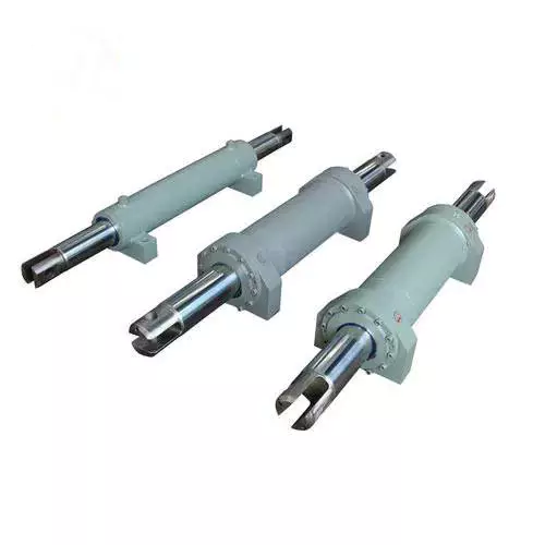
| Material: | Steel |
|---|---|
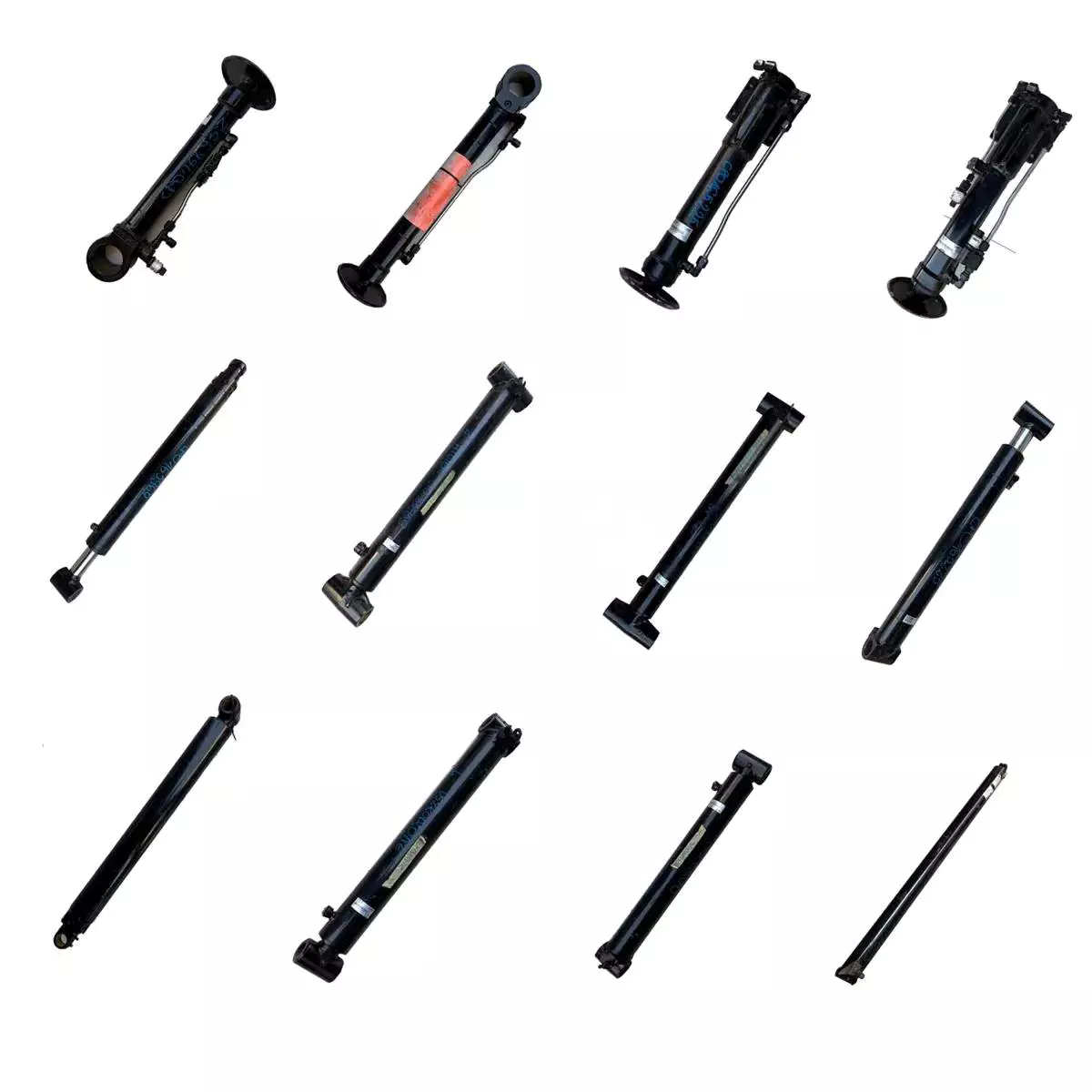
| Usage: | Oxygen Gas and Nitrogen Cylinder |
| Structure: | Gas – Liquid Damping Cylinder |
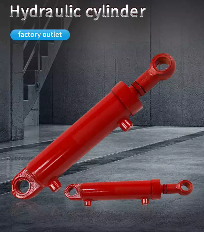
| Power: | Hydraulic |
| Standard: | Standard |
| Pressure Direction: | Single-acting Cylinder |
| Customization: |
Available
|
|
|---|
How do hydraulic cylinders handle the challenges of precise positioning and control?
Hydraulic cylinders are designed to handle the challenges of precise positioning and control with a combination of engineering principles and advanced control systems. These challenges often arise in applications where accurate and controlled movements are required, such as in industrial automation, construction, and material handling. Here’s a detailed explanation of how hydraulic cylinders overcome these challenges:
1. Fluid Power Control:
– Hydraulic cylinders utilize fluid power control to achieve precise positioning and control. The hydraulic system consists of a hydraulic pump, control valves, and hydraulic fluid. By regulating the flow of hydraulic fluid into and out of the cylinder, operators can control the speed, direction, and force exerted by the cylinder. The fluid power control allows for smooth and accurate movements, enabling precise positioning of the hydraulic cylinder and the attached load.
2. Control Valves:
– Control valves play a crucial role in handling the challenges of precise positioning and control. These valves are responsible for directing the flow of hydraulic fluid within the system. They can be manually operated or electronically controlled. Control valves allow operators to adjust the flow rate of the hydraulic fluid, controlling the speed of the cylinder’s movement. By modulating the flow, operators can achieve fine control over the positioning of the hydraulic cylinder, enabling precise and accurate movements.
3. Proportional Control:
– Hydraulic cylinders can be equipped with proportional control systems, which offer enhanced precision in positioning and control. Proportional control systems utilize electronic feedback and control algorithms to precisely regulate the flow and pressure of the hydraulic fluid. These systems provide accurate and proportional control over the movement of the hydraulic cylinder, allowing for precise positioning at various points along its stroke length. Proportional control enhances the cylinder’s ability to handle complex tasks that require precise movements and control.
4. Position Feedback Sensors:
– To achieve precise positioning, hydraulic cylinders often incorporate position feedback sensors. These sensors provide real-time information about the position of the cylinder’s piston rod. Common types of position feedback sensors include potentiometers, linear variable differential transformers (LVDTs), and magnetostrictive sensors. By continuously monitoring the position, the feedback sensors enable closed-loop control, allowing for accurate positioning and control of the hydraulic cylinder. The feedback information is used to adjust the flow of hydraulic fluid to achieve the desired position accurately.
5. Servo Control Systems:
– Advanced hydraulic systems employ servo control systems to handle the challenges of precise positioning and control. Servo control systems combine electronic control, position feedback sensors, and proportional control valves to achieve high levels of accuracy and responsiveness. The servo control system continuously compares the desired position with the actual position of the hydraulic cylinder and adjusts the flow of hydraulic fluid to minimize any positional error. This closed-loop control mechanism enables the hydraulic cylinder to maintain precise positioning and control, even under varying loads or external disturbances.
6. Integrated Automation:
– Hydraulic cylinders can be integrated into automated systems to achieve precise positioning and control. In such setups, the hydraulic cylinders are controlled by programmable logic controllers (PLCs) or other automation controllers. These controllers receive input signals from various sensors and use pre-programmed logic to command the hydraulic cylinder’s movements. The integration of hydraulic cylinders into automated systems allows for precise and repeatable positioning and control, enabling complex sequences of movements to be executed with high accuracy.
7. Advanced Control Algorithms:
– Advancements in control algorithms have also contributed to the precise positioning and control of hydraulic cylinders. These algorithms, such as PID (Proportional-Integral-Derivative) control, adaptive control, and model-based control, enable sophisticated control strategies to be implemented. These algorithms consider factors such as load variations, system dynamics, and environmental conditions to optimize the control of hydraulic cylinders. By employing advanced control algorithms, hydraulic cylinders can compensate for disturbances and achieve precise positioning and control over a wide range of operating conditions.
In summary, hydraulic cylinders overcome the challenges of precise positioning and control through the use of fluid power control, control valves, proportional control, position feedback sensors, servo control systems, integrated automation, and advanced control algorithms. By combining these elements, hydraulic cylinders can achieve accurate and controlled movements, enabling precise positioning and control in various applications. These capabilities are essential for industries that require high precision and repeatability in their operations, such as industrial automation, robotics, and material handling.
Ensuring Stable Performance of Hydraulic Cylinders Under Fluctuating Loads
Hydraulic cylinders are designed to provide stable performance even under fluctuating loads. They achieve this through various mechanisms and features that allow for efficient load control and compensation. Let’s explore how hydraulic cylinders ensure stable performance under fluctuating loads:
- Piston Design: The piston inside the hydraulic cylinder plays a crucial role in load control. It is typically equipped with seals and rings that prevent leakage of hydraulic fluid and ensure effective transfer of force. The piston design may incorporate features such as stepped or tandem pistons, which provide enhanced load-bearing capabilities and improved stability by distributing the load across multiple surfaces.
- Cylinder Cushioning: Hydraulic cylinders often incorporate cushioning mechanisms to minimize the impact and shock caused by fluctuating loads. Cushioning can be achieved through various methods, such as adjustable cushion screws, hydraulic cushioning valves, or elastomeric cushioning rings. These mechanisms slow down the piston’s movement near the end of the stroke, reducing the impact and preventing sudden stops that could lead to instability.
- Pressure Compensation: Fluctuating loads can result in pressure variations within the hydraulic system. To ensure stable performance, hydraulic cylinders are equipped with pressure compensation mechanisms. These mechanisms maintain a consistent pressure level in the system, regardless of load changes. Pressure compensation can be achieved through the use of pressure relief valves, compensating pistons, or pressure-compensated flow control valves.
- Flow Control: Hydraulic cylinders often incorporate flow control valves to regulate the speed of the cylinder’s movement. By controlling the flow rate of hydraulic fluid, the cylinder’s motion can be adjusted to match the changing load conditions. Flow control valves allow for smooth and controlled movement, preventing abrupt changes that could lead to instability.
- Feedback Systems: To ensure stable performance under fluctuating loads, hydraulic cylinders can be integrated with feedback systems. These systems provide real-time information on the cylinder’s position, velocity, and force. By continuously monitoring these parameters, the hydraulic system can make immediate adjustments to maintain stability and compensate for load fluctuations. Feedback systems can include position sensors, pressure sensors, or load sensors, depending on the specific application.
- Proper Sizing and Selection: Ensuring stable performance under fluctuating loads starts with proper sizing and selection of hydraulic cylinders. It is crucial to choose cylinders with appropriate bore size, rod diameter, and stroke length to match the anticipated load conditions. Oversized or undersized cylinders can lead to instability and reduced performance. Proper sizing also involves considering factors such as the required force, speed, and duty cycle of the application.
In summary, hydraulic cylinders ensure stable performance under fluctuating loads through features such as piston design, cushioning mechanisms, pressure compensation, flow control, feedback systems, and proper sizing and selection. These mechanisms and considerations allow hydraulic cylinders to provide consistent and controlled movement, even in dynamic load conditions, resulting in reliable and stable performance.
What safety precautions should be followed when working with hydraulic cylinders?
Working with hydraulic cylinders requires strict adherence to safety precautions to prevent accidents, injuries, and damage to equipment or property. Hydraulic systems operate under high pressures and involve moving parts, which can pose serious hazards if not handled properly. Here’s a detailed explanation of the safety precautions that should be followed when working with hydraulic cylinders:
1. Training and Knowledge:
– Ensure that personnel working with hydraulic cylinders have received adequate training and possess a thorough understanding of hydraulic system operation, maintenance, and safety protocols. Proper training should cover topics such as hydraulic principles, pressure ratings, safe work practices, and emergency procedures. Only trained and authorized personnel should be allowed to handle hydraulic cylinders.
2. Wear Personal Protective Equipment (PPE):
– Always wear appropriate personal protective equipment when working with hydraulic cylinders. This may include safety glasses, gloves, protective clothing, and steel-toed boots. PPE helps protect against potential hazards, such as hydraulic fluid leaks, flying debris, or accidental contact with moving parts.
3. Hydraulic System Inspection:
– Before working with hydraulic cylinders, inspect the entire hydraulic system for any signs of damage, leaks, or loose connections. Check hydraulic hoses, fittings, valves, and cylinders for integrity and secure fastening. If any issues are detected, the system should be repaired or serviced before operation.
4. Relieve Pressure:
– Before performing any maintenance or disassembly on a hydraulic cylinder, it is crucial to relieve the pressure in the system. Follow the manufacturer’s instructions to properly release pressure and ensure that the hydraulic cylinder is depressurized before starting any work. Failure to do so can result in sudden and uncontrolled movement of the cylinder or hydraulic lines, leading to serious injuries.
5. Lockout/Tagout Procedures:
– Implement lockout/tagout procedures to prevent accidental energization of the hydraulic system while maintenance or repair work is being conducted. Lockout/tagout involves isolating the energy source, such as shutting off the hydraulic pump and locking or tagging the controls to prevent unauthorized operation. This procedure ensures that the hydraulic cylinder remains in a safe, non-operational state during maintenance activities.
6. Use Proper Lifting Techniques:
– When working with heavy hydraulic cylinders or components, use proper lifting techniques and equipment to avoid strain or injury. Hydraulic cylinders can be heavy and awkward to handle, so ensure that lifting equipment, such as cranes or hoists, is properly rated and used correctly. Follow safe lifting practices, including securing the load and maintaining a stable lifting posture.
7. Hydraulic Fluid Handling:
– Handle hydraulic fluid with care and follow proper procedures for fluid filling, transfer, and disposal. Avoid contact with the skin or eyes, as hydraulic fluid may be hazardous. Use appropriate containers and equipment to prevent spills or leaks. If any hydraulic fluid comes into contact with the skin or eyes, rinse thoroughly with water and seek medical attention if necessary.
8. Regular Maintenance:
– Perform regular maintenance and inspections on hydraulic cylinders to ensure their safe and reliable operation. This includes checking for leaks, inspecting seals, monitoring fluid levels, and conducting periodic servicing as recommended by the manufacturer. Proper maintenance helps prevent unexpected failures and ensures the continued safe use of hydraulic cylinders.
9. Follow Manufacturer Guidelines:
– Always follow the manufacturer’s guidelines, instructions, and recommendations for the specific hydraulic cylinders and equipment being used. Manufacturers provide important safety information, maintenance schedules, and operational guidelines that should be strictly adhered to for safe and optimal performance.
10. Emergency Preparedness:
– Be prepared for potential emergencies by having appropriate safety equipment, such as fire extinguishers, first aid kits, and emergency eyewash stations, readily available. Establish clear communication channels and emergency response procedures to promptly address any accidents, leaks, or injuries that may occur during hydraulic cylinder operations.
By following these safety precautions, individuals working with hydraulic cylinders can minimize the risk of accidents, injuries, and property damage. It is essential to prioritize safety, maintain awareness of potential hazards, and ensure compliance with relevant safety regulations and industry standards.


editor by CX 2023-10-26