Product Description
DSW brand medical oxygen cylinder
Model Number: ISO229-50-200
Material: Steel 34Crmo4
new seamless steel gas cylinder for N2,O2
Industrial nitrogen Gas
Pressure: High
Place of Origin: China (Mainland)
Brand Name: CHINAMFG seamless steel cylinder
Thickness of seamless:4.3mm
weight of seamless: 50kg
TP:200KG/CM2
PW:300KG/CM2
| 40L and 50L medical oxygen cylinders | |||||||
| Type | (mm) Outside Diameter |
(L) Water Capacity |
(mm) () Height (Withoutvalve) |
(Kg) (,) Weight(Without valve,cap) |
(Mpa) Working Pressure |
(mm) Design Wall Thickness |
Material Grades |
| ISO232-40-150 | 219 | 40 | 1167 | 43 | 200 | 5.2 | 37Mn |
| ISO232-47-150 | 47 | 1351 | 49 | ||||
| ISO232-50-150 | 50 | 1430 | 51.6 | ||||
| ISO232-40-200 | 232 | 40 | 1156 | 44.9 | 200 | 5.2 | 34CrMo4 |
| ISO232-46.7-200 | 46.7 | 1333 | 51 | ||||
| ISO232-47-200 | 47 | 1341 | 51.3 | ||||
| ISO232-50-200 | 50 | 1420 | 54 | ||||
| EN232-40-210 | 232(TPED) | 40 | 1156 | 44.9 | 230 | 5.8 | 34CrMo4 |
| EN232-46.7-210 | 46.7 | 1333 | 51 | ||||
| EN232-47-210 | 47 | 1341 | 51.3 | ||||
| EN232-50-210 | 50 | 1420 | 54 | ||||
| EN232-40-230 | 40 | 1156 | 44.9 | 230 | 5.8 | 34CrMo4 | |
| EN232-46.7-230 | 46.7 | 1333 | 51 | ||||
| ISO232-47-230 | 47 | 1341 | 51.3 | ||||
| ISO232-50-230 | 50 | 1420 | 54 | ||||
| ISO267-40-150 | 267 | 40 | 922 | 43.3 | 150 | 5.8 | 37Mn |
| ISO267-50-150 | 50 | 1119 | 51.3 | ||||
| 50L (10M3) Oxygen cylinder record of hydrostatic test pressure time ≥ 60S | ||||||||
| S.N | Serial No. | ()The weight without valve&cap(kg) | Volumetric Capacity(L) | Total expansion(ml) | Permanent expansion(ml) | Percent of Permanent to totalexpanison(%) | Test Pressure 250Bar | Lot and Batch No. |
| 351 | 18Y571 001 | 56.4 | 50.2 | 215.1 | 3.1 | 1.4 | 300 | 18Y571 |
| 352 | 18Y571 002 | 56.5 | 50.4 | 208.5 | 3.0 | 1.4 | 300 | 18Y571 |
| 353 | 18Y571 003 | 56.4 | 50.2 | 212.2 | 2.8 | 1.3 | 300 | 18Y571 |
| 354 | 18Y571 004 | 56.2 | 50.0 | 214.9 | 3.0 | 1.4 | 300 | 18Y571 |
| 355 | 18Y571 005 | 56.3 | 50.2 | 212.2 | 2.8 | 1.3 | 300 | 18Y571 |
| 356 | 18Y571 006 | 56 | 50.0 | 219.8 | 2.9 | 1.3 | 300 | 18Y571 |
| 357 | 18Y571 007 | 56.3 | 50.1 | 213.5 | 2.8 | 1.3 | 300 | 18Y571 |
| 358 | 18Y571 008 | 56.1 | 50.4 | 210.5 | 3.2 | 1.5 | 300 | 18Y571 |
| 359 | 18Y571 009 | 56.1 | 50.5 | 212.1 | 2.8 | 1.3 | 300 | 18Y571 |
| 360 | 18Y571 571 | 55.9 | 50.7 | 203.5 | 3.1 | 1.5 | 300 | 18Y571 |
| 361 | 18Y571 011 | 56.1 | 50.0 | 214.9 | 2.8 | 1.3 | 300 | 18Y571 |
| 362 | 18Y571 012 | 56.6 | 50.4 | 210.5 | 3.2 | 1.5 | 300 | 18Y571 |
| 363 | 18Y571 013 | 55.9 | 50.2 | 211.2 | 2.7 | 1.3 | 300 | 18Y571 |
| 364 | 18Y571 014 | 55.8 | 50.2 | 211.2 | 3.1 | 1.5 | 300 | 18Y571 |
| 365 | 18Y571 015 | 55.9 | 50.1 | 211.6 | 2.8 | 1.3 | 300 | 18Y571 |
| 366 | 18Y571 016 | 55.6 | 50.0 | 213.9 | 3.2 | 1.5 | 300 | 18Y571 |
| 367 | 18Y571 017 | 56.1 | 50.0 | 213.9 | 2.8 | 1.3 | 300 | 18Y571 |
| 368 | 18Y571 018 | 56.3 | 50.0 | 213.9 | 3.0 | 1.4 | 300 | 18Y571 |
| 369 | 18Y571 019 | 56.1 | 50.6 | 205.8 | 3.2 | 1.6 | 300 | 18Y571 |
| 370 | 18Y571 571 | 55.8 | 50.3 | 209.9 | 2.6 | 1.2 | 300 | 18Y571 |
| 371 | 18Y571 571 | 55.7 | 50.0 | 213.9 | 3.1 | 1.4 | 300 | 18Y571 |
| 372 | 18Y571 571 | 55.7 | 50.1 | 212.6 | 2.8 | 1.3 | 300 | 18Y571 |
| 373 | 18Y571 571 | 56 | 50.1 | 211.6 | 2.8 | 1.3 | 300 | 18Y571 |
| 374 | 18Y571 571 | 56.5 | 50.1 | 214.5 | 2.8 | 1.3 | 300 | 18Y571 |
| 375 | 18Y571 571 | 56.1 | 50.3 | 210.8 | 2.8 | 1.3 | 300 | 18Y571 |
| 376 | 18Y571 026 | 56.2 | 50.3 | 210.8 | 3.2 | 1.5 | 300 | 18Y571 |
| 377 | 18Y571 571 | 56.3 | 50.0 | 214.9 | 3.1 | 1.4 | 300 | 18Y571 |
| 378 | 18Y571 571 | 56 | 50.2 | 212.2 | 2.9 | 1.4 | 300 | 18Y571 |
| 379 | 18Y571 571 | 56.7 | 50.2 | 211.2 | 3.0 | 1.4 | 300 | 18Y571 |
| 380 | 18Y571 030 | 56.1 | 50.1 | 213.5 | 2.6 | 1.2 | 300 | 18Y571 |
| 381 | 18Y571 031 | 55.9 | 50.0 | 213.9 | 2.8 | 1.3 | 300 | 18Y571 |
| 382 | 18Y571 032 | 55.9 | 54.0 | 163.8 | 2.6 | 1.6 | 300 | 18Y571 |
| 383 | 18Y571 033 | 56.3 | 50.1 | 212.6 | 2.8 | 1.3 | 300 | 18Y571 |
| 384 | 18Y571 034 | 55.9 | 50.5 | 207.1 | 3.2 | 1.5 | 300 | 18Y571 |
| 385 | 18Y571 035 | 56.3 | 50.3 | 210.8 | 3.0 | 1.4 | 300 | 18Y571 |
| 386 | 18Y571 036 | 56.3 | 50.4 | 208.5 | 2.8 | 1.3 | 300 | 18Y571 |
| 387 | 18Y571 037 | 55.7 | 50.3 | 211.8 | 2.7 | 1.3 | 300 | 18Y571 |
| 388 | 18Y571 038 | 56 | 50.0 | 217.9 | 2.8 | 1.3 | 300 | 18Y571 |
| 389 | 18Y571 039 | 56.1 | 50.0 | 212.9 | 3.1 | 1.5 | 300 | 18Y571 |
| 390 | 18Y571 040 | 56.2 | 50.2 | 211.2 | 2.8 | 1.3 | 300 | 18Y571 |
| 391 | 18Y571 041 | 56.6 | 50.6 | 205.8 | 2.6 | 1.3 | 300 | 18Y571 |
| 392 | 18Y571 042 | 56.4 | 50.1 | 212.6 | 3.3 | 1.6 | 300 | 18Y571 |
| 393 | 18Y571 043 | 56.2 | 50.2 | 213.2 | 2.6 | 1.2 | 300 | 18Y571 |
| 394 | 18Y571 044 | 55.8 | 50.4 | 208.5 | 2.7 | 1.3 | 300 | 18Y571 |
| 395 | 18Y571 045 | 55.7 | 50.0 | 213.9 | 2.8 | 1.3 | 300 | 18Y571 |
| 396 | 18Y571 046 | 56.4 | 50.0 | 213.9 | 3.3 | 1.5 | 300 | 18Y571 |
| 397 | 18Y571 047 | 56.1 | 50.2 | 213.2 | 3.2 | 1.5 | 300 | 18Y571 |
| 398 | 18Y571 048 | 56.2 | 50.0 | 213.9 | 2.7 | 1.3 | 300 | 18Y571 |
| 399 | 18Y571 049 | 56.4 | 50.1 | 214.5 | 3.1 | 1.4 | 300 | 18Y571 |
| 400 | 18Y571 050 | 56 | 50.4 | 210.5 | 3.2 | 1.5 | 300 | 18Y571 |
100% new high quality seamless steel pipe from Bao Shan Iron co.,ltd (Baosteel).
Total 5 working line make 3000pcs per day for oxygen gas cylinder, argon gas cylinder, helium gas cylinder, Nitrogen gas cylinder , Co2 gas cylinder, N2O gas cylinder..etc
China top 1 advanced heat treatment machine. And China top 1 internal polishing machine to make high purity gas cylinder with 99.999% oxygen gas, helium gas, N2O gas and argon gas….
100% Hydrostatic prssure test and leakage test to keep the quality
Advanced automatic spraying working line make the spraying at high top quality , no any bubble , without shrinkage and distoration .
Japan imported shoulder marking machine make it the most qualified ones .
DSW seamless gas cylinder have nice appearance shoulders because we use shape-correction machine treatment make the cylinder shoulder most beautiful shape which other supplier can’t be compared.
Laboratory test standard ISO9809-3 and ISO9809-1, DOT-3AA, EN1964,GB5099 ..etc
Place of Origin: China
| Material: | Steel |
|---|---|
| Usage: | Nitrogen |
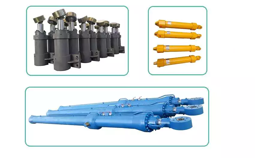
| Structure: | General Cylinder |
| Power: | Hydraulic |
| Standard: | Standard |
| Pressure Direction: | Single-acting Cylinder |
| Customization: |
Available
|
|
|---|
How do hydraulic cylinders compare to other methods of force generation like electric motors?
Hydraulic cylinders and electric motors are two different methods of force generation with distinct characteristics and applications. While both hydraulic cylinders and electric motors can generate force, they differ in terms of their working principles, performance attributes, and suitability for specific applications. Here’s a detailed comparison of hydraulic cylinders and electric motors:
1. Working Principle:
– Hydraulic Cylinders: Hydraulic cylinders generate force through the conversion of fluid pressure into linear motion. They consist of a cylinder barrel, piston, piston rod, and hydraulic fluid. When pressurized hydraulic fluid enters the cylinder, it pushes against the piston, causing the piston rod to extend or retract, thereby generating linear force.
– Electric Motors: Electric motors generate force through the conversion of electrical energy into rotational motion. They consist of a stator, rotor, and electromagnetic field. When an electrical current is applied to the motor’s windings, it creates a magnetic field that interacts with the rotor, causing it to rotate and generate torque.
2. Force and Power:
– Hydraulic Cylinders: Hydraulic cylinders are known for their high force capabilities. They can generate substantial linear forces, making them suitable for heavy-duty applications that require lifting, pushing, or pulling large loads. Hydraulic systems can provide high force output even at low speeds, allowing for precise control over force application. However, hydraulic systems typically operate at lower speeds compared to electric motors.
– Electric Motors: Electric motors excel in providing high rotational speeds and are commonly used for applications that require rapid motion. While electric motors can generate significant torque, they tend to have lower force output compared to hydraulic cylinders. Electric motors are suitable for applications that involve continuous rotary motion, such as driving conveyor belts, rotating machinery, or powering vehicles.
3. Control and Precision:
– Hydraulic Cylinders: Hydraulic systems offer excellent control over force, speed, and positioning. By regulating the flow of hydraulic fluid, the force and speed of hydraulic cylinders can be precisely controlled. Hydraulic systems can provide gradual acceleration and deceleration, allowing for smooth and precise movements. This level of control makes hydraulic cylinders well-suited for applications that require precise positioning, such as in industrial automation or construction equipment.
– Electric Motors: Electric motors also offer precise control over speed and positioning. Through motor control techniques such as varying voltage, frequency, or pulse width modulation (PWM), the rotational speed and position of electric motors can be accurately controlled. Electric motors are commonly used in applications that require precise speed control, such as robotics, CNC machines, or servo systems.
4. Efficiency and Energy Consumption:
– Hydraulic Cylinders: Hydraulic systems can be highly efficient, especially when properly sized and designed. However, hydraulic systems typically have higher energy losses due to factors such as fluid leakage, friction, and heat generation. The overall efficiency of a hydraulic system depends on the design, component selection, and maintenance practices. Hydraulic systems require a hydraulic power unit to pressurize the hydraulic fluid, which consumes additional energy.
– Electric Motors: Electric motors can have high efficiency, especially when operated at their optimal operating conditions. Electric motors have lower energy losses compared to hydraulic systems, primarily due to the absence of fluid leakage and lower friction losses. The overall efficiency of an electric motor depends on factors such as motor design, load conditions, and control techniques. Electric motors require an electrical power source, and their energy consumption depends on the motor’s power rating and the duration of operation.
5. Environmental Considerations:
– Hydraulic Cylinders: Hydraulic systems typically use hydraulic fluids that can pose environmental concerns if they leak or are not properly disposed of. The choice of hydraulic fluid can impact factors such as biodegradability, toxicity, and potential environmental hazards. Proper maintenance and leak prevention practices are essential to minimize the environmental impact of hydraulic systems.
– Electric Motors: Electric motors are generally considered more environmentally friendly since they do not require hydraulic fluids. However, the environmental impact of electric motors depends on the source of electricity used to power them. When powered by renewable energy sources, such as solar or wind, electric motors can offer a greener solution compared to hydraulic systems.
6. Application Suitability:
– Hydraulic Cylinders: Hydraulic cylinders are commonly used in applications that require high force output, precise control, and durability. They are widely employed in industries such as construction, manufacturing, mining, and aerospace. Hydraulic systems are well-suited for heavy-duty applications, such as lifting heavy objects, operating heavy machinery, or controlling large-scale movements.
– Electric Motors: Electric motors are widely used in various industries and applications that require rotational motion, speed control, and precise positioning. They are commonly found in appliances, transportation, robotics, HVAC systems, and automation. Electric motorsare suitable for applications that involve continuous rotary motion, such as driving conveyor belts, rotating machinery, or powering vehicles.In summary, hydraulic cylinders and electric motors have different working principles, force capabilities, control characteristics, efficiency levels, and application suitability. Hydraulic cylinders excel in providing high force output, precise control, and durability, making them ideal for heavy-duty applications. Electric motors, on the other hand, offer high rotational speeds, precise speed control, and are commonly used for applications that involve continuous rotary motion. The choice between hydraulic cylinders and electric motors depends on the specific requirements of the application, including the type of motion, force output, control precision, and environmental considerations.
Ensuring Stable Performance of Hydraulic Cylinders Under Fluctuating Loads
Hydraulic cylinders are designed to provide stable performance even under fluctuating loads. They achieve this through various mechanisms and features that allow for efficient load control and compensation. Let’s explore how hydraulic cylinders ensure stable performance under fluctuating loads:
- Piston Design: The piston inside the hydraulic cylinder plays a crucial role in load control. It is typically equipped with seals and rings that prevent leakage of hydraulic fluid and ensure effective transfer of force. The piston design may incorporate features such as stepped or tandem pistons, which provide enhanced load-bearing capabilities and improved stability by distributing the load across multiple surfaces.
- Cylinder Cushioning: Hydraulic cylinders often incorporate cushioning mechanisms to minimize the impact and shock caused by fluctuating loads. Cushioning can be achieved through various methods, such as adjustable cushion screws, hydraulic cushioning valves, or elastomeric cushioning rings. These mechanisms slow down the piston’s movement near the end of the stroke, reducing the impact and preventing sudden stops that could lead to instability.
- Pressure Compensation: Fluctuating loads can result in pressure variations within the hydraulic system. To ensure stable performance, hydraulic cylinders are equipped with pressure compensation mechanisms. These mechanisms maintain a consistent pressure level in the system, regardless of load changes. Pressure compensation can be achieved through the use of pressure relief valves, compensating pistons, or pressure-compensated flow control valves.
- Flow Control: Hydraulic cylinders often incorporate flow control valves to regulate the speed of the cylinder’s movement. By controlling the flow rate of hydraulic fluid, the cylinder’s motion can be adjusted to match the changing load conditions. Flow control valves allow for smooth and controlled movement, preventing abrupt changes that could lead to instability.
- Feedback Systems: To ensure stable performance under fluctuating loads, hydraulic cylinders can be integrated with feedback systems. These systems provide real-time information on the cylinder’s position, velocity, and force. By continuously monitoring these parameters, the hydraulic system can make immediate adjustments to maintain stability and compensate for load fluctuations. Feedback systems can include position sensors, pressure sensors, or load sensors, depending on the specific application.
- Proper Sizing and Selection: Ensuring stable performance under fluctuating loads starts with proper sizing and selection of hydraulic cylinders. It is crucial to choose cylinders with appropriate bore size, rod diameter, and stroke length to match the anticipated load conditions. Oversized or undersized cylinders can lead to instability and reduced performance. Proper sizing also involves considering factors such as the required force, speed, and duty cycle of the application.
In summary, hydraulic cylinders ensure stable performance under fluctuating loads through features such as piston design, cushioning mechanisms, pressure compensation, flow control, feedback systems, and proper sizing and selection. These mechanisms and considerations allow hydraulic cylinders to provide consistent and controlled movement, even in dynamic load conditions, resulting in reliable and stable performance.
How do hydraulic cylinders ensure precise and controlled movement in equipment?
Hydraulic cylinders are widely used in various equipment and machinery to provide precise and controlled movement. They utilize hydraulic fluid and mechanical components to achieve accurate positioning, smooth operation, and reliable control. Here’s a detailed explanation of how hydraulic cylinders ensure precise and controlled movement in equipment:
1. Hydraulic Principle:
– Hydraulic cylinders operate based on Pascal’s law, which states that pressure exerted on a fluid is transmitted equally in all directions. The hydraulic fluid is contained within the cylinder, and when pressure is applied, it acts on the piston, generating force. By controlling the pressure and flow of hydraulic fluid, the movement of the cylinder can be precisely regulated, allowing for accurate and controlled motion.
2. Force and Load Management:
– Hydraulic cylinders are designed to handle specific loads and forces. The force generated by the hydraulic cylinder depends on the hydraulic pressure and the surface area of the piston. By adjusting the pressure, the force output can be controlled. This allows for precise management of the load and ensures that the cylinder can handle the required force without exerting excessive or insufficient force. Proper load management contributes to the precise and controlled movement of the equipment.
3. Control Valves:
– Control valves play a crucial role in regulating the flow and direction of hydraulic fluid within the cylinder. These valves allow operators to control the extension and retraction of the cylinder, adjust the speed of movement, and stop or hold the cylinder at any desired position. By manipulating the control valves, precise and controlled movement can be achieved, enabling operators to position equipment accurately and perform specific tasks with precision.
4. Flow Control:
– Hydraulic cylinders incorporate flow control valves to manage the rate of hydraulic fluid flow. These valves control the speed of the cylinder’s extension and retraction, allowing for smooth and controlled movement. By adjusting the flow rate, operators can precisely control the speed of the cylinder, ensuring that it moves at the desired rate without sudden or erratic movements. Flow control contributes to the overall precision and control of the equipment’s movement.
5. Position Sensing:
– To ensure precise movement, hydraulic cylinders can be equipped with position sensing devices such as linear transducers or proximity sensors. These sensors provide feedback on the position of the cylinder, allowing for accurate position control and closed-loop control systems. By continuously monitoring the position, the equipment’s movement can be controlled with high accuracy, enabling precise positioning and operation.
6. Proportional Control:
– Advanced hydraulic systems utilize proportional control technology, which allows for precise and fine-tuned control of the hydraulic cylinder’s movement. Proportional valves, often operated by electronic control systems, provide variable flow rates and pressure adjustments. This technology enables precise control of speed, force, and position, resulting in highly accurate and controlled movement of the equipment.
7. Cushioning and Damping:
– Hydraulic cylinders can incorporate cushioning and damping mechanisms to ensure smooth and controlled movement at the end of the stroke. Cushioning features, such as adjustable cushions or shock absorbers, reduce the impact and decelerate the cylinder before reaching the end of the stroke. This prevents abrupt stops and minimizes vibrations, contributing to precise and controlled movement.
8. Load Compensation:
– Some hydraulic systems utilize load compensation mechanisms to maintain precise movement even when the load varies. Load-sensing systems monitor the load demand and adjust the hydraulic pressure and flow accordingly to meet that demand. This compensation ensures that the equipment’s movement remains accurate and controlled, regardless of changes in the applied load.
In summary, hydraulic cylinders ensure precise and controlled movement in equipment through the application of hydraulic principles, force and load management, control valves, flow control, position sensing, proportional control, cushioning and damping mechanisms, and load compensation. These features and technologies allow operators to achieve accurate positioning, smooth operation, and reliable control, enabling equipment to perform tasks with precision and efficiency. The combination of hydraulic power and careful design considerations ensures that hydraulic cylinders deliver precise and controlled movement in a wide range of industrial applications.


editor by CX 2023-12-03